2001 jeep cherokee instrument cluster wiring diagram. jeep 2019-05-03
SOLVED: What relay controls the instrument cluster?

I went out and got the following from another expert. It would be nice to know for sure where its going though and i assume that diagram called for will show it in better detail. . So those wires have been completly replaced and protected properly. I bought the manual from Chilton but it is not in that book. Disconnect the in line connector C101.
Jeep Grand Cherokee repair manual

Again, it will still be the Purple wire with Black stripe. Connect scan tool to data link connector. I decide just to check on the off chance the reboot fixed the issue and low and behold when I hit the key it was 75 degrees outside. If resistance is less than 2 ohms, replace instrument cluster printed circuit board or speedometer and tachometer. Side note: I will have pictures posted as soon as i figure out how to post them If you take of all that electrical tape and sleve, you will see that by having the wires in the same loom tied together real tight like this, that the isualation on the wires has gone bad due to the temp changes and this causes the wires including the alterantor wires that are in that loom as well arc across to each other. Consumer took vehicle to dealer. I just checked through another area of my database and it seems the speed sensor is systated as on the side of transaxle, near firewall, maybe you can dheck that out to confirm, just out of curiosity and for future reference and some portion of testing requires unplugging the conections.
SOLVED: Wiring diagram jeep YJ speedometer

Disconnect the vehicle battery under the hood. Another issue we found was a celinod in the trans that was defective due to this proply causeing the down shift issue will know soon as we are soon to be putting the car back together. Second time the gas gauge quit and then started working again. If voltage is not present, check vehicle speed sensor harness connector and wiring. Take the screws out of the plastic panel under the column and rempve it. A more sure way to check if a fuse is broken is to buy a fuse tester.
The Famous Jeep Grand Cherokee Electrical Problem
If connector and wiring are okay, go to next step. Locate the connector to the crank sensor, it runs beside the distributor, with the key to the on position unplug the connector and see if the gauges come back on. The back-up lamps are controlled by the neutral safety switch located on the passenger side of the trans. . Take the screws out of the metal sub panel under the colmn and remove it. Refer to Testing for Intermittent Conditions and Poor Connections in Wiring Systems. Battery voltage should be present.
Fuse diagram for Jeep Cherokee 2001

You will find two, one for the hazzard lights and the other for the signals. If the volt reading is varying between 0. I would look at Park Lights and Instrument Cluster fuses. The overhead console displays 'lines' instead of information. Common Question How and why did my fuse go bad? You can save this pic file to your individual computer. This allows me to backprobe the connector with my voltmeter.
Jeep Cherokee Electrical

This image was uploaded on 11-04-2018. Refer to Testing for Continuity in Wiring Systems. Normally I remove the connector from it's bracket and pull it down for better access. If you find a unit with a reading close to what yours reads, that's fine. Pop open the hood and it's on the passenger side in the vicinity of your coolant bottle. Let me know if you make it this far and then I will send the last 9 steps.
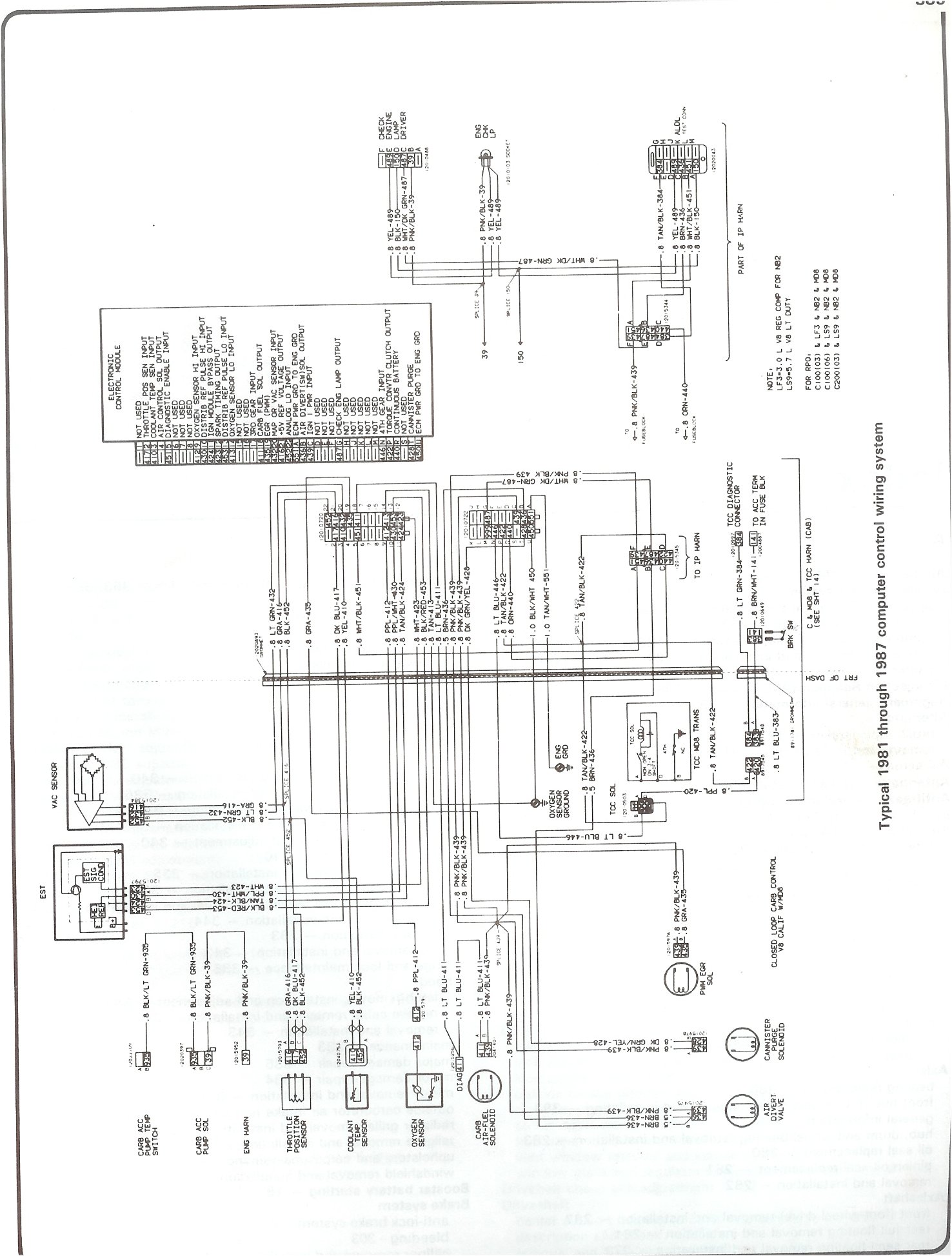
1995 to 2001 Jeep Cherokee XJ Wiring Diagrams

It is easily visible without removing any panels. The reason it is not working is because when you replace the module on the passenger side you remove the receiver that is matched to your fob with it. It is a black box that is located between the battery and the engine coolant tank. I missed that in the connector location list the last time i checked. As sugg'd by others, I disconctd battery for a time. If the bus voltage is always near 0 volts, a different method will work. You need to replace the coolant temperature sending unit.
Jeep Cherokee 1997

For anyone wondering what i am working on here it's a Horizon Navigation NavMate system. When in doubt, put a new battery in. It's called the flasher and it is located on the driver side below the dash where the buzzer is located. My brother in law called this morning and gave me the same symptoms he is having with his Jeep. In addition, this image also has a width 708 and length 1024 piksel.
1995 to 2001 Jeep Cherokee XJ Wiring Diagrams
If connectors and wiring are okay, go to next step. I had similar systems to those described here in my 1999 Grand Cherokee. Amazing how one can get tied up doing things and suddenly its four months later. I went to Advantage Auto Parts to determine the fuses for the windows and they were all good. I have the NavMate 2. Refer to Instrument Cluster Replacement Test the continuity from the vehicle speed sensor signal 4K circuit at the instrument cluster electrical connector to the in line connector C101. If battery voltage is not present, check harness connectors and harness wiring between instrument cluster and ignition switch for damage.
Jeep Cherokee 1997

This indicates that a module one of the vehicle computers is pulling the bus voltage too high, causing interference and a loss of communication between modules, which leads to the symptoms you are experiencing. At the same time the air bag light comes on. Thanks very much for your info. Sep 06, 2012 wiring from the sensor on the rear diff? Blue Park Lights 7 10 Amp Red Interior Lights 8 15 Amp Lt. Before you dive in with a , you will want to obtain a free wiring diagram for your specific model.