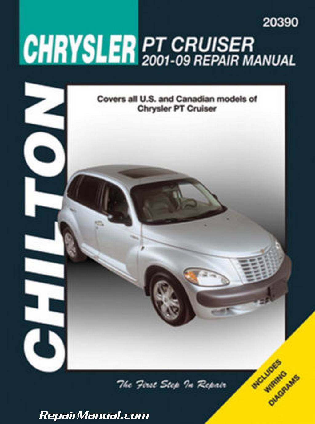
2003 pt cruiser repair manual pdf. Chrysler PT Cruiser 2003 Workshop Manual PDF 2019-04-25
2003 Chrysler PT Cruiser Service Repair Workshop Manual DOWNLOAD
These manuals make it easy for any skill level with these very easy to follow. All information in this manual is based on the latest product information at the time of publication. Repair this circuit as required; whether a wiring short, incorrect switch adjustment, or a component failure is at fault. The flywheel also incor- porates an integral starter ring gear. Refer to the Body section of this manual for the pro- cedure. To measure rotor runout on the vehicle, first remove the tire and wheel assembly. The relay is contained within a small, rectangular, molded plastic housing and is connected to all of the required inputs and outputs by five integral male spade-type terminals that extend from the bottom of the relay base.
2003 Pt Cruiser Sport

. The If the brakes are applied at anytime during a trac- addition of aftermarket electrical equipment car tion control cycle, the brake lamp switch triggers the. The stabilizer bar interconnects the rear axle with the frame rails of the vehicle Fig. The generator is located above the oil filter and axle shaft Fig. It is this level of detail, along with hundreds of photos and illustrations, that guide the reader through each service and repair procedure. Replace the engine air cleaner filter.
2003 PT Cruiser Service Repair Manual DOWNLOAD
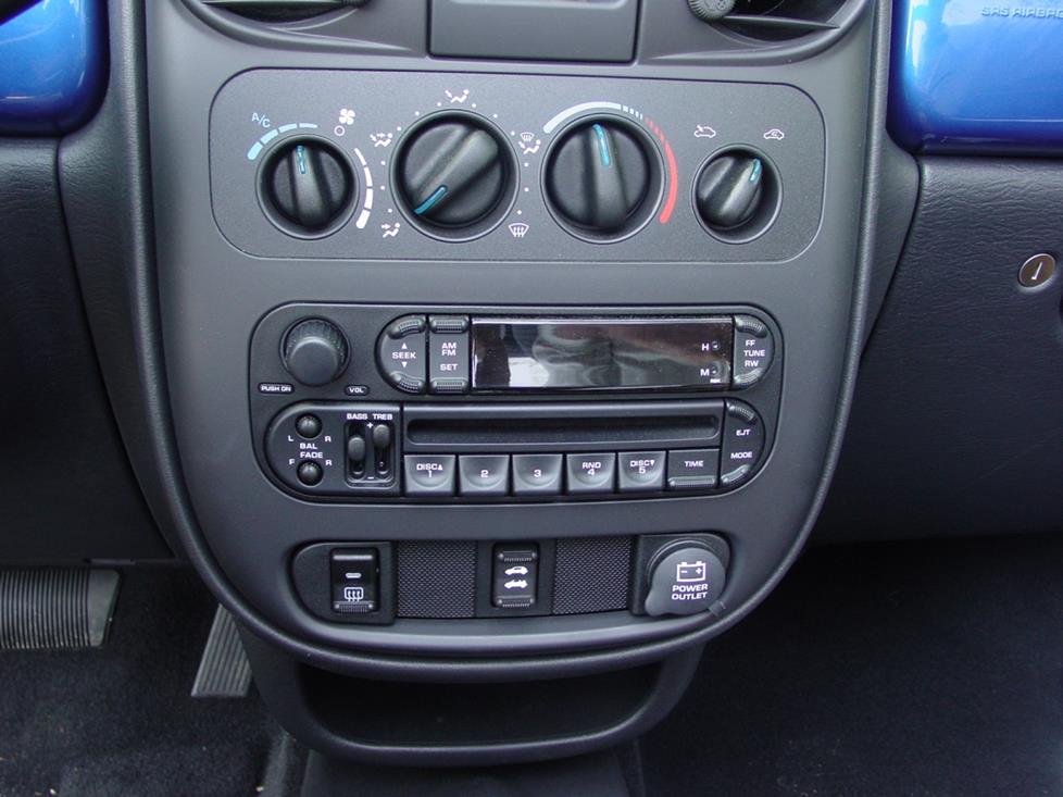
Over torquing could cause cracks in magnet. No shipping fee, no waiting on postal delivery, you can start doing your repairs right away! Tighten sensor 2 Relocate the power steering return hose. The car owner faces 3 white-faced gauges set up in personal cylinders, with speedometer center, tachometer appropriate and energy and water temperature kept. These vehicles only utilize the starter inhibit interlock feature. Using this repair manual is an inexpensive way to keep your vehicle working properly. The result is the hot rod many needed when the Cruiser was basically unveiled.
2003 Chrysler PT Cruiser Service Repair Workshop Manual DOWNLOAD

Shock Absorber Lower — Mounting Bolt Shock Absorber Upper — Mounting Bolt Stabilizer Bar Cushion — Retainer Bolt Stabilizer Bar Link Bolts And — Nuts Watts Link Bell Crank Pivot —. One of the two hydraulic circuits is 1. With no mechanical assistance or added force, attempt to move the grease fitting. All repair procedures are covered A-Z. No fluid service or sys- tem bleeding should be required, unless the hydraulic system has lost an excessive amount of fluid and has ingested air into the master or slave cylinder assembly.
2003 PT Cruiser Service Repair Manual DOWNLOAD
Toe-out on turns is the relative positioning of the Steering axis inclination is the angle between a front wheels while steering through a turn Fig. There is also a vent valve in the center of the cap. If machining the drum will cause the drum to exceed maximum allowable diameter, do not machine the brake drum. Use care not to over-fill reservoir and spill fluid into engine compartment. This may be accom- panied by the visible loss of grease. Refer to replacing the wheel speed sensor or tone wheel. Remove the rear pivot bolt attaching the lower control arm to the front suspension crossmem- ber and frame rail.
2003 Chrysler PT Cruiser Service Repair Workshop Manual DOWNLOAD

If excessive resistance is The battery cables are large gauge, stranded cop- found in the battery cable connections, the connec- per wires sheathed within a heavy plastic or syn-. If an extreme condition is indicated, the lamp will be illuminated. Diagrams a complete list of. Install and tighten brake booster contacting pedals. Refer to Engine, Structural Collar Removal and Installation. Please consult your local distributor for those items you may require. Receiver, Special Tool 8405-1, installed, over the arm, 21.
2003 Chrysler PT Cruiser Owners Manual

Do not exceed sixteen volts while charging a battery. For 2003, there is much more blaze under the hood. Repair Manual comes with comprehensive details regarding technical data. Over-tightening can distort the drive plate hub For all clutch chatter complaints, perform the fol- causing excessive runout. Remove six 6 pressure plate-to-fly- wheel bolts Fig. Remove the washer behind the strut from the torque strut bolt.
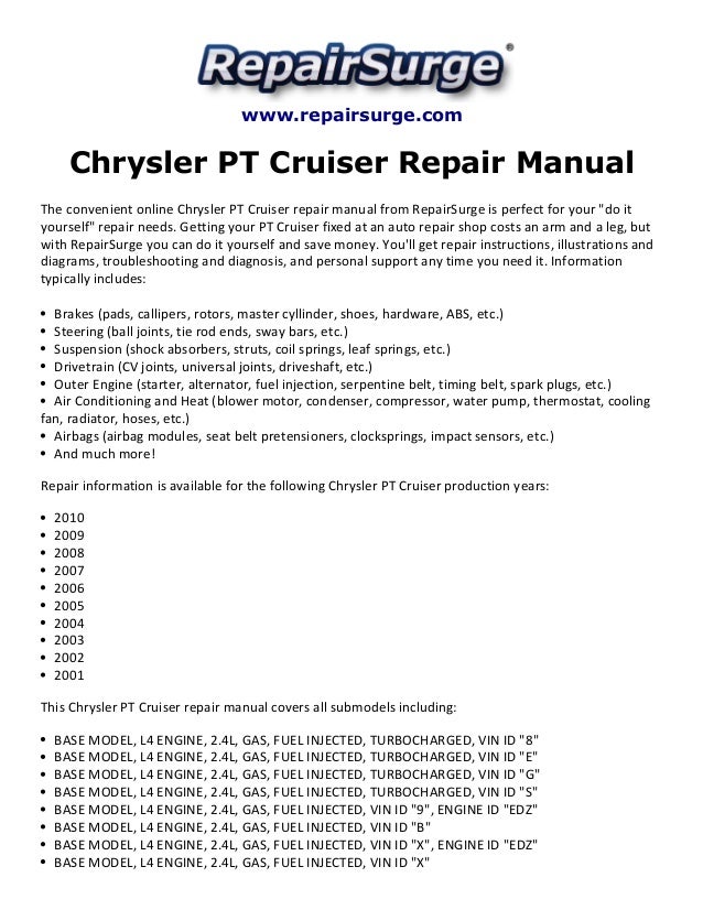
Chrysler PDF Workshop and Repair manuals
The diagram shows no wheel spin or slip occurring relative to the speed of the vehicle. This is accomplished by the friction and clamping force generated when the spring loaded pressure 2. Program with technical information of engine manuals, chassis and body, maintenance and user of Mercedes Benz cars W124 Series manufactured between 1986 and 2014. To achieve the cross camber reading, as viewed from above the vehicle Fig. A battery charger that supplies twenty amperes or more will require a shorter charg- ing time.
2003 Chrysler PT Cruiser Auto Repair Manual
Using this repair manual is an inexpensive way to keep your vehicle working properly. Replace the engine air cleaner filter. Holding the bolts in ing installed back in the arbor press with the smaller place tighten the nuts to a torque of 53 N·m 40 ft. Each manual provides step-by-step instructions based on the complete disassembly of the machine. Rear brake drum out of round or 1. Useful for performing repair work on all models of the series mentioned.
2003 Pt Cruiser Sport

Clean and inspect the brake support plate and shoe adjuster screw. Improper torque may result in Torque lug nuts to 135 N·m 100 ft. The spiral plate battery is completely, per- manently sealed. Each manual provides step-by-step instructions based on the complete disassembly of the machine. Parking brake warning switch on 2. If the genera- tor fails for any reason, the entire assembly must be replaced.