Acura tsx manual pdf. 2013 Acura TSX User Manual Owners Pdf 2019-03-16
2005 Acura TSX Owners Manual PDF

Owner's Guides and Manuals are viewable on any computer or device with. Reinstall the return hose on the reservoir. In some states, part of the emissions testing is to make sure these codes are set to complete. If resistance is less than one ohm, go to next step. Tighten the steering joint bolt to specified torque.
Acura TSX Workshop & Owners Manual

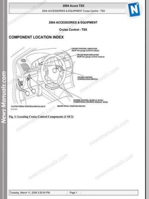
The pressure control valve is not available separately. When window reaches bottom position, continue to depress switch for 2 seconds, then release switch. To connect, hold pawl-side connector half, and press on back of sleeve-side connector half in direction shown. Refer to the System Diagram to see the functional layout of the system. Be careful not to damage the brake lines with the pinion shaft.
2012 Acura TSX Owners Manual Pdf

Rotate cable reel counterclockwise about 3 turns until arrow mark on cable reel label points straight up. Release tabs and remove cable reel from column. Repair or replace the pump. Connect a hose B of suitable diameter to the disconnected return hose, and put the hose end in a suitable container. If voltage is less than one volt, go to next step. Disconnect auxiliary battery or power source, if equipped. Carefully push on the clip portions of the mirror holder until the mirror holder locks into place.
ACURA TSX MANUAL Pdf Download.
Coat the surface of the steering rack A with power steering fluid. Remove the valve seal ring and O-ring. Open the pressure control valve A fully. Before installing the steering gearbox, make sure that no power steering fluid is on the mating surface of the gearbox and a front suspension subframe. Remove seat belt upper and lower anchor bolts.
2005 Acura TSX Owners Manual PDF

If continuity exists, replace right seat belt buckle. Be sure that the joint bolt is securely in the groove in the pinion shaft. Install the wave washer B. If fuse blows again, check for short to ground in fuse No. Check for unusual steering effort through the complete turning range. Remove the steering gearbox mounting bolts on the left gearbox mount, and remove the steering stiffener plate A. Measure resistance between seat belt buckle switch connector terminals No.
Acura TSX Service Repair Manual Download
Connect the backprobe adapters A to the stacking patch cords B , and connect the cords to a digital multimeter. Pry out the lock pin A , and pull the pedal pin B out of the yoke. Remove bottom, then upper B-pillar trim panels. Repair or replace as necessary. Wash hands and rinse well with water after handling deployed air bag assemblies and seat belt pretensioners. If voltage is less than 0.
2005 Acura TSX Owners Manual PDF

Hold the gearbox housing using a C-clamp commercially available A and wooden blocks B. Defogger Test Canada : 5. Install the cam ring A with the. Lower the engine speed and let it idle. The control unit receives signals from each sensor.
ACURA TSX MANUAL Pdf Download.
Disconnect right and left seat belt pretensioners. Carefully pry out retainer with flat-tip screwdriver. The boot must not have a gap at the boot installation sections B. Install the pump preload spring A in the pump housing. Test-drive the vehicle under stop-and-go conditions with short periods of steady cruise.
ACURA TSX MANUAL Pdf Download.

Wipe off any grease contamination from the ball joint tapered section and threads. The amount of air is regulated by engine coolant temperature. Measure resistance between ground and seat wire harness connector terminal No. Reconnect battery and turn ignition on. If G601 is okay, replace appropriate wire harness. Intake Air Bypass Control Thermal Valve When the engine is cold, the intake air bypass control thermal valve sends air to the injector.