Amp bias problem. MOSFET Amplifier Circuit using an Enhancement MOSFETBasic Electronics Tutorials 2019-03-07
Op

I worked on it for 3 days and checked the wiring twice each day. I installed a 25k pot between the phase splitter plate tubes to balance out using a 1k tone. What do you guys think could be happening?? Did they bias the amp to suit, I asked? Yeah, the meter set to measure current is basically a short to ground the way you're using it. When it comes to tube amps the idea is basically the same, however, instead of fuel and air we are dealing with electrical current. Your final alternative, assuming you have the space for it, is to make a small printed circuit board, install the trim pot of your choice on it and use hard wiring to solder the lot to your amp. The original circuit hints at 15 mA current. You could then simply replace it with another of the same type of any make and providing it was a good one, the Bias Engine would automatically set the bias to match the remaining valves and the show would go on.
Op
In closing, I stress once again - the actual benefits and limits will vary depending on the design, but there is no doubt that you will hear a difference just by changing the trim pots if your unit uses poor quality ones, and you will be able to increase the quiescent current somewhat, which will again offer some benefits. Other than a slight drop in volume, you might not even notice that anything had gone wrong! A mosfet device has three different regions of operation. Download artists' signature amps, or try out the latest and most popular matched amp models created by your fellow guitarists. Make a note of it. Suppose also that the plate voltage of my amp is 400 volts. I do find it strange, never the less, that the following has been conspicuous by its absence. Again problem was in the tube.
Amp Bias Problem
This over abundance of free electrons within the p-type substrate causes a conductive channel to appear or grow as the electrical properties of the p-type region invert, effectively changing the p-type substrate into a n-type material allowing channel current to flow. If not I'd suspect a duff valve and check by substitution. What type of resistors did you bet for the bias monitor resistors? The first thing you want to adjust is the quiescent current. . Please don't ask how I know this. That way, most problems associated with class A and B are avoided - no massive heat sinks, power supplies and numerous power devices, much improved efficiency, yet most of the crossover nasties are also avoided and speed need not be critically compromised.
Solving Bias Problems in a Marshall DSL
Or go for the 0. Unless you like the smell of your meter going up in smoke. Was that with three different meters? Carefull in there, there's 400+ volts going thru the meter. Author Some cookies are required for secure log-ins but others are optional for functional activities. As a general rule, the factory set point will usually be the lowest acceptable point. Non-Adjustable Fixed Bias With this type of biasing, as the name would imply, the bias can't be easily adjusted.
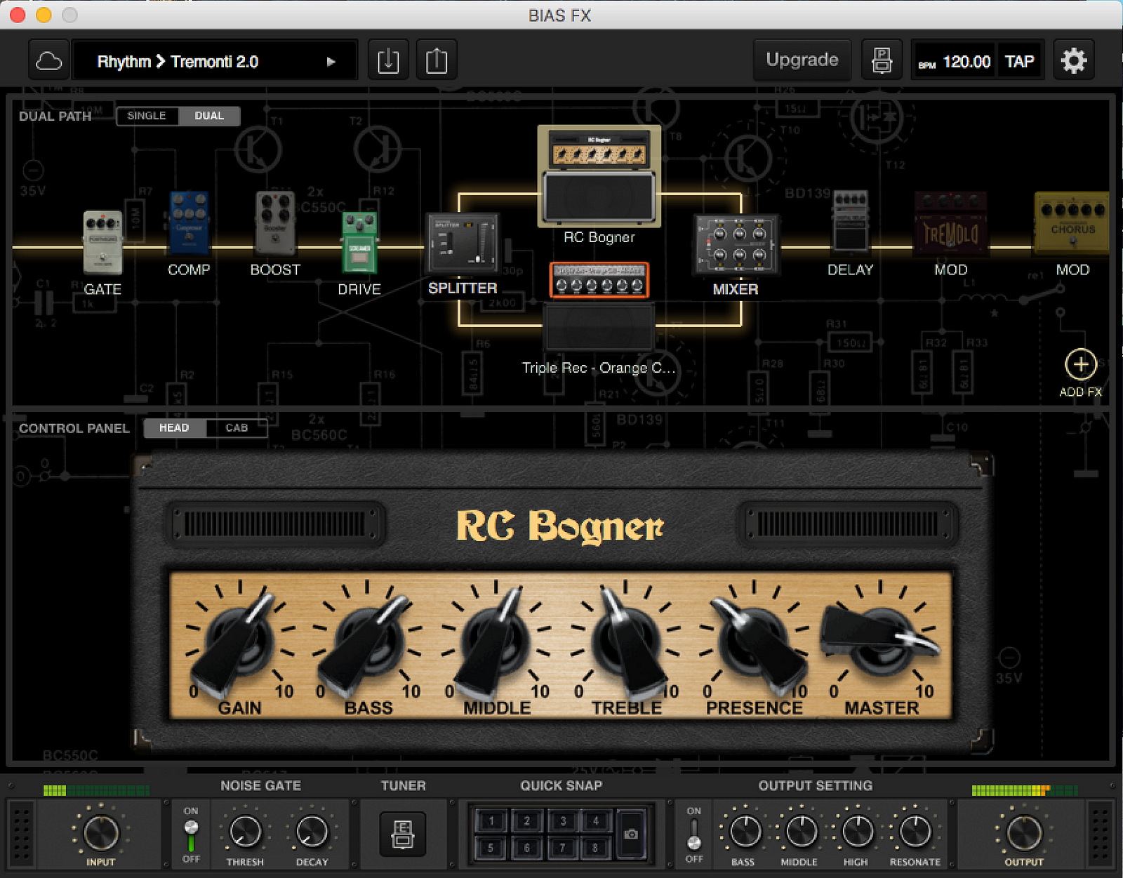
BIAS Amp 2

It is wise to go back and re-check the readings after doing all of the tubes, as sometimes ones previously biased can be effected by as much as 10-20%. Bad trim pots do that. The red leads are connected to the test meters where the anode currents can then be read. I've put together a veroboard prototype of the circuit and i ran into a little problem with biasing. This started as a tube screamer clone and it is almost which has a transistor buffer after the op-amp. Basically, the bias is pre-set to a fixed point based on the performance of a given set of tubes. I took that totally the wrong way.
Solving Bias Problems in a Marshall DSL

Thus, a casual lab test using an ac-coupled scope might not detect this problem, and the circuit will not fail until hours later. They are plugged into the valve bases, and the valves are then plugged into them. Check the bias capacitor first!!! Also, you will reach a point above which you can go on increasing the quiescent current, but will receive very little, if any, sonic benefit; this simply means that you have reached and gone over the truly optimal point. With few exceptions they choose the 70%. Adjustable Fixed Bias Adjustable fixed bias certainly sounds like an oxymoron, but it is actually the best way to describe this type of biasing. More current less volts, less current more volts.
Output Tube Biasing Problems
You can buy from any reputable valve supplier, such as here in the U. For this reason, they will normally function pretty well with a wide range of tubes without needing any adjustment. I tried several op-amps but the problem stays. I thought he was using the trimmer to get extremes. It's unlikely the screen resistors are 270 ohm,more likely 470 ohm. He is stating that the voltage above R28 has a 23 volt variance relative to the bias trim pot adjustment.
What is tube amp bias?

So, if one channel uses say 10 mA of quiescent current and the other uses 50 mA, I'll bet good money that unit will have poor imaging and a rather flat sound stage due to gross channel mismatch. The amount of drain current that flows through this n-channel therefore depends on the gate-source voltage and one of the many measurements we can take using a mosfet is to plot a transfer characteristics graph to show the i-v relationship between the drain current and the gate voltage as shown. So I followed the gnd wire from the resistor to the pcb and found that the trace goes through a 22 ohm resistor just before the ground conection to the mains input. What I actually did was to adjust the bias in order to bring the unmatched set of valves, within safer operating parameters. You need to take out the chassis and measure that bias voltage at pins 5 of each power tube.