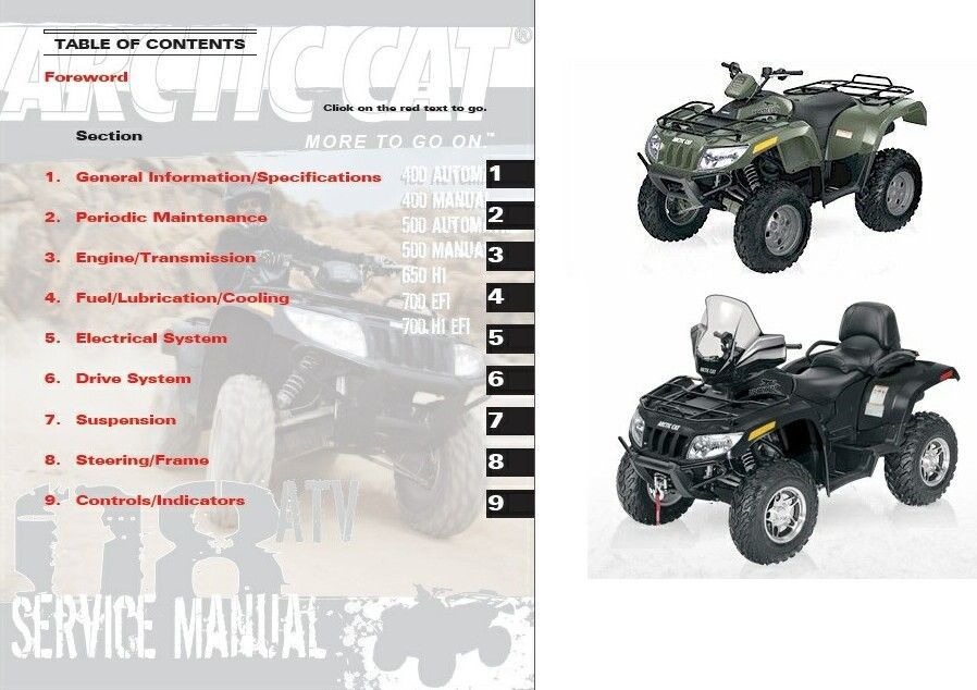
Arctic cat atv 2007 service manual. 2007 Arctic Cat ATV Workshop Service Repair Manual 2019-04-08
2007 Arctic Cat 700 Diesel ATV service manual

Check the thickness of each of the brake pads as follows. Place the two tappet covers with O-rings into position; then tighten the covers securely. If thickness of either brake pad is less than 1. Remove the front camshaft support housing; then from the throttle control arm; then remove the remove the governor flyweight assembly. Repeat steps 6 and 7 for the second injector if it was removed. Using this repair manual is an inexpensive way to keep your vehicle working properly. Remove four machine screws and flanged nuts frame; then remove the belly panel.
2007 Arctic Cat ATV Workshop Service Repair Manual

Secure the vehicle on a support stand to elevate retainer, and remove the spring. Spark Plug A light brown insulator indicates that a plug is cor- rect. Burnishing Brake Pads Brake pads both hydraulic and auxiliary must be burnished to achieve full braking effectiveness. A low-pressure gauge is provided in the tool kit to measure the air pressure in the tires. Using a new O-ring, coat the flange of the cam- shaft bearing retainer and the camshaft support bearing with clean engine oil and install into the cylinder head. Valve Stem Runout max 0. Connecting Rod big end width 25 mm 0.
2007 Arctic Cat 700 Diesel ATV service manual

Such efficiency not only helps build consumer confidence but also saves time and labor. Expansion room must be maintained in the tank par- ticularly if the tank is filled with cold gasoline and then moved to a warm area. Rotate the ignition switch to the lights position; the headlights and taillight should illuminate. In a crisscross pattern starting from the center 32. Piston Diameter 15 mm 0.
ARCTIC CAT 700 DIESEL ATV 2007 SERVICE MANUAL Pdf Download.

Check the level of coolant in the coolant expan- sion tank located under the right front fender. Remove the vent plugs; then if necessary fill the battery with distilled water to the upper level indicated on the battery. The numbers are scribed onto the gears: the ring gear has the number on the oppo- site side of the gears, and the pinion gear has the number on the end of the pinion gear shaft by the splines. Bolt length must not exceed 91 mm. Shock absorber eyelet bushings not worn, deteriorated, cracked, or missing. Adjusting Throttle Cable To adjust the throttle cable free-play, follow this procedure.
2007 Arctic Cat 250 repair manual

Care must be taken that all calibrated nuts, cap screws, and bolts are tightened to specifications see Section 10. While holding the adjuster dial at the proper clearance setting, tighten the jam nut securely! Remove the recoil starter assembly; then remove the valve timing inspection plug and the cylinder head cover. Inspect shift cam detent stopper and shift cam detent for worn rollers or broken spring. When servicing battery in enclosed space, keep the area well-ventilated. Remove the cylinder head from the cylinder, remove the gasket, and account for two alignment pins.
Arctic Cat ATV Service Manuals

The service technician should become familiar with the operation and construction of each component or system by carefully studying the complete manual. Connect the wiring connectors to the temperature frame and tighten the mounting hardware securely. Ignition switch — engine will start. No spark is present or required for ignition. Piston Pin Bore max 23. If bearing cups are loose, joint;. Proper aim is ing procedure.
2007 Arctic Cat 700 EFI
Gears worn - rubbing 1. Remove the pinch screw and lock nut securing the gear shift lever; then remove the gear shift lever from the shaft on the engine. Oil trapped in these areas could result in a false valve clearance reading. Disconnect the crankcase vent hose from the air cleaner housing. Remove the E-clip from the transmission shift arm; then disconnect the shifter linkage. Using a thin pry-bar or screwdriver, work the movable face sleeve upward and free of the O-rings; then remove the sleeve.
Arctic Cat Prowler 2007 Service manual
Remove the shift shaft H ; then remove the two 7. These oils can adversely affect clutch operation. Other maintenance after break-in should include checking of all prescribed adjustments and tightening of all fasteners. Piston Pin Bore max 23. Shift Fork Thickness 1 and 2 5.
2007 Arctic Cat ATV Workshop Service Repair Manual

The technician should use discretion and sound judgment. Install the knuckle to the upper and lower ball joints and secure with the two cap screws. Never use a bench vise without jaw protection or severe damage to the connecting rod and engine will occur. Brakelight Switch Handlebar Control To access the connector, remove the access panel. Flush the radiator with water to remove any con- taminants. Inspect the bearing halves, bearing caps, and bear- ing housings for cracks or wear.