Aw50-42le solenoid. Automatic Transmission Diagnosis 2019-01-18
AW50

If voltage is consistently high or low, check wiring for an open or short circuit. Apply service and parking brakes. Commercial use and publishing at other websites of these items is prohibited. Start engine and ensure idle speed is adjusted properly. Shake driving mode selector to see if there are loose parts in the switch.
AW50

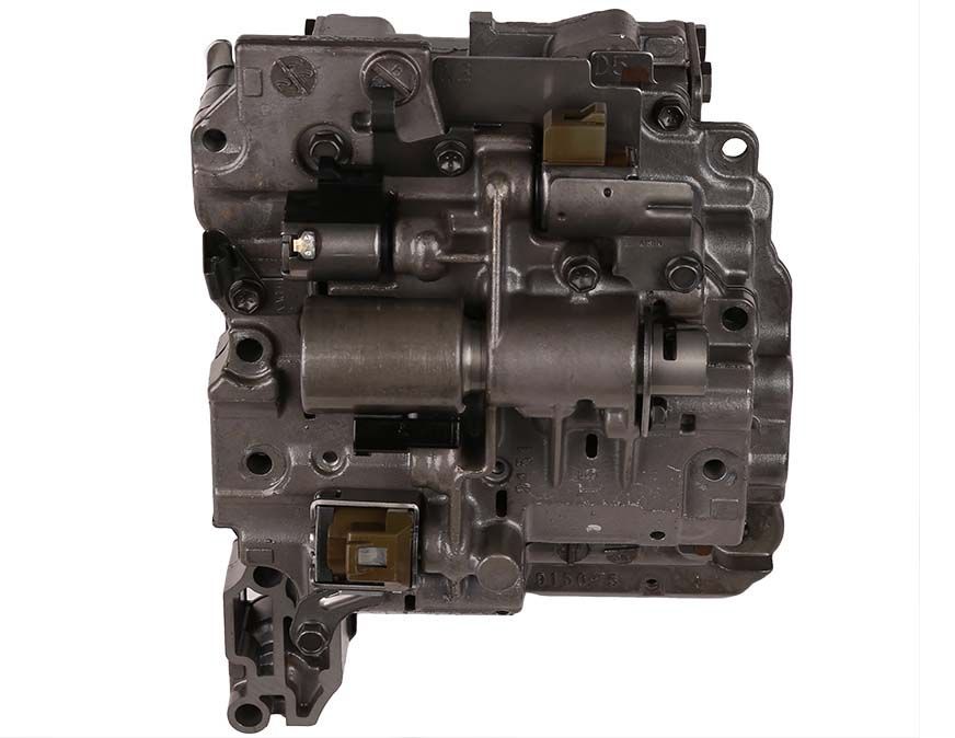
Remove air cleaner housing to access transaxle connector. Place control valve assembly on clean workbench. Connect ohmmeter between terminals in solenoid connector. If voltage is not as specified, check wiring and repair as necessary. Manual shifting is possible into all other shift lever positions. Short To Voltage In Lock-Up Solenoid Circuit 332 ………………….
Automatic Transmission Diagnosis

If indentation does not align with mark, go to next step. Connect ohmmeter between pin on solenoid and ground. Connect voltmeter between transaxle connector terminal No. Remove sound insulator to gain access to brake switch, located at top of brake lever. If solenoid operates, check wiring for an intermittent short circuit. For solenoid locations, See Fig.
AW50

If ohmmeter reads 10-15 ohms, transmission is probably okay. Remove oil pan Torx screws and remove oil pan. Check line pressure at idle and record pressure reading. For transaxle connector terminal locations, See Fig. Signal indicates that torque limiting is taking place.
Volvo 850 automatic transmission diagnosis & wiring diagram

Perform time measurement several times and calculate average time. If voltage readings are not okay, go to next step. If resistance is not as specified, replace oil temperature sensor. Remove transaxle oil pipe and drain fluid. Block one front wheel and spin other wheel rapidly. If solenoid operates, check wiring for an intermittent short circuit. If ohmmeter does not read 10-15 ohms, go to next step.
VOLVO AW 50
If voltage readings are okay, gear position sensor is okay. If resistance is not as specified, replace solenoid. Disconnect switch connector from switch. Remove 9 control valve assembly bolts, noting length and location of bolts for installation reference. If Hz frequency reading shows wide fluctuations, go to next step.
AW50

If ohmmeter reads infinite resistance, replace gear position sensor. Remove sensor from control shaft. Check solenoid function by using test mode No. Manufacturer does not provide mechanical trouble shooting information. Connect ohmmeter between measuring unit terminals No. Testing is performed in a cycle in which each component is activated 6 times with a short delay between each activation.
SAAB AW 50
Remove 2 accumulator pistons and 3 springs, and 3 modulator valves and springs. Load signal should be about 35. Battery voltage should be present. This function checks component operation, wiring and connections in each circuit. Accelerate vehicle and check for transaxle slippage. If ohmmeter does not read about 10-15 ohms, replace solenoid. Remove transmission cable from rod arm.
SAAB AW 50

If voltage is not as specified, replace sensor. If voltmeter does not read 4-7 volts, replace speedometer. A 3-second interval separates each series of flashes. Ohmmeter should indicate approximately zero ohms. In case of internal malfunction, manufacturer recommends replacing transaxle as an assembly. Ensure codes have been cleared by pressing button once. Output signals can be monitored by watching or listening to appropriate component to be activated.
Volvo 850 automatic transmission diagnosis & wiring diagram
Compare all readings to specification. Tighten oil pan Torx screws to 18 ft. Test drive vehicle and ensure all upshifts and downshifts occur at specified speeds. If terminal contact is okay, check Black ground wire for good terminal contact. If solenoid operates, check wiring for an intermittent short circuit. Economy Mode ………… 244 Sport ………………. Check for voltage at diagnostic connector terminal No.