General electric induction motor wiring diagram. Need help with wiring an electric motor 2019-04-14
Need help with wiring an electric motor

A guard of some kind should protect humans or other creatures from touching it while it is operating. They informed me all I needed to do was to connect the black, and yellow wires for power. When a capacitor is so introduced, the voltage lags the current by some phase angle. The electric current is usually conducted to the coils of the stator from an external circuit, but is frequently induced in the coils of the rotor by changes in the magnetic flux linkage due to the varying currents in the stator windings. The name plate of the motor tells how much power it will deliver at the shaft, the voltage to be applied, and the full load current the motor will take from the line in operation. Of the baser metals, copper is the best conductor. These motors can be explained best by referring to the series motor shown in figure 17, A, in which the same current flows through the rotor armature as the stator field.
Need Schematic For old GE Electric Motor....
It is reversed in the same manner as is the split-phase motor. The set screw should turn down onto the key or flattened part of the shaft. For this reason a belt should be made just tight enough to prevent slipping, and the tension should be released when the belt is not in use. Figure 8, A, shows a cross section of a sleeve bearing with ring-oiling feature. I just thought about one here if all else fails. That is why you use the model number to look it the wiring up.
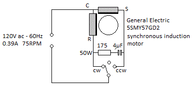
How to wire single phase motor with start/run/permanent capacitors.
Never grip the shaft with a pipe wrench or similar tool as that roughens the surface. Fans are often mounted this way and vacuum cleaners always. Oil-lubricated bearings are usually built with reservoirs that will hold enough oil for several weeks. However, daily inspection of the oil and the oiling mechanism is desirable in order to keep the reservoir filled to the proper level and to see that the rings are functioning. An iron wire has from 6 to 10 times the resistance of a copper wire of equal size and length. They will still work at 250 volts.
Industrial Motors and Generators
A deep-well plunger pump is an example of this type of load. Set the motor where it will not be in the way. These motors have inherently constant speed within the limits of their rated loads. I immediatly unplugged once I saw smoke. This is known as a short circuit. If the load is removed from the rotor, it runs faster, more voltage is generated and less current flows in the rotor circuit.
Need help with wiring an electric motor

As I said the motor came on then started to smoke shortly after. Alternating current—Current that flows first in one direction and then in the opposite direction at regular intervals. It is evident from the phasor diagram that the current through the starter winding Is leads the voltage V by a small angle and the current through the main winding Im lags the applied voltage. Is my recepticle putting out to many volts or maybe not enough? No current will flow around the winding except through an external connection because the voltages around the circuit are balanced. Here is what I would try, considering that I can not successfully google a wiring diagram: See if one of the brown capacitor wires has 0. Both the overcurrent and undervoltage devices may be connected to the magnetic switch so that they open only the circuit of the magnetic coil, thus allowing the switch to drop open by gravity.
Capacitor Start Motors: Diagram & Explanation of How a Capacitor is Used to Start a Single Phase Motor

Although motors are usually tested before they leave the factory, the insulation may sometimes fail in which case the motor frame may become alive. It may be built for operating in any desired position. Take care to see that the shafts of vertical motors are vertical. For example: In a single-phase system but one current flows, while in a three-phase system three currents flow. The capacitor usually connects to 2 brown wires or a brown and brown with white stripe. It has already been pointed out that both overloading and undervoltage cause the motor to draw excessive current from the line and that overcurrents cause excessive heating.
Ge Ac Wiring Diagram General Electric Single Phase Motor And Motors Inside Diagrams

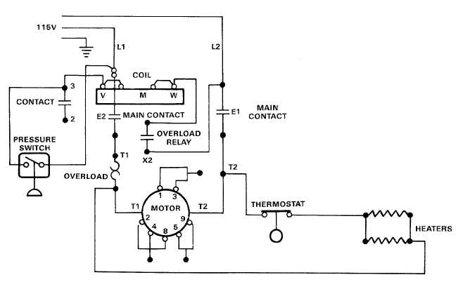
The capacitor start-and-run motor differs from the capacitor start motor in that a condenser is connected into the running circuit as well as into the starting circuit. The motor came to me, already wired for standard 110V, but it pulls 16 amps like this, and we need to get it hooked up to 220V. The motor automatically regulates the current within the limits of its rating so that it uses only slightly more than is required to drive its load. If it is desirable to control the motor from some distance, a push button and magnetic switch should be used. A force is set up between the conductors carrying the current and the magnetic field, thus producing a torque in the direction of rotation. Hence, too much oil may be as bad as too little. Figure 13 shows a motor connected in an electric circuit.
Industrial Motors and Generators

By thinking of these flux lines as stretched rubber bands it can be seen from the diagram that the conductor will tend to move toward the left. The purpose is to confine the magnetic flux to given locations within the motor since iron will support many times as much magnetism as the same volume of air The pole in the alternating-current motor is made of laminated iron. Materials that will not carry current readily are known as insulators. It is 1 coulomb per second. The yoke, b, which forms the stationary magnetic path, is made up of laminations or thin sheets. If a resistance start split phase then whichever has the start winding will be somewhat lower resistance. We want to make a site helpful for many people.