Massey ferguson 383 repair manual. Massey Ferguson MF 362 365 375 383 390 390 T 398 Tractor Shop Manual 2019-05-12
www.littleboyblu.com Massey Ferguson 383 tractor information
It also includes a guide for ordering parts. The track rod of all models assures that both left and right wheels turn in unison and the distance between ends of track rod establishes front wheel toe-in. Axle end play should be 0. The procedure for removing and installing ends is self-evident. Lubrication Mainshaft Output Shaft and Gears. Install seal 20 and key 14 then locate steering arm on top of spindle.
Massey Ferguson MF 362 365 375 383 390 390 T 398 Tractor Shop Manual

When replacing fasteners, always use the same type part number fastener as removed. On all models, complete assembly by reversing the removal procedure. The work can only be carried out if the owner has the necessary hand and special service tools to complete the job. Rotate wheels and remeasure to be sure that wheels are not bent giving incorrect reading. If wheels are reversed, they must be moved to opposite sides oftractor to maintain correct tire tread direction. To make small toe-in adjustments, remove track adjusting bolt 2 , loosen rod end clamp bolt 3 orjam nut, then turn track rod until toe-in is correct.
Massey Ferguson MF 383 Operators Manual

To adjust toe-in, loosen the locknuts at each end of the track tie rod, then turn i. Reverse removal procedure when as- sembling. Information on the troubleshooting, servicing specification lists, tightening torque, checking and adjusting, disassembling and assembling and servicing which cover procedures, precautions, factory specifications and allowable limits. Which Manual Do I Need? Re- move key 14 and seal 20 from top of spindle, then lower spindle out of axle extension 19. On all models, it may be necessary to ream bushings after installation.
Massey Ferguson MF 375 Workshop Service Repair Manual

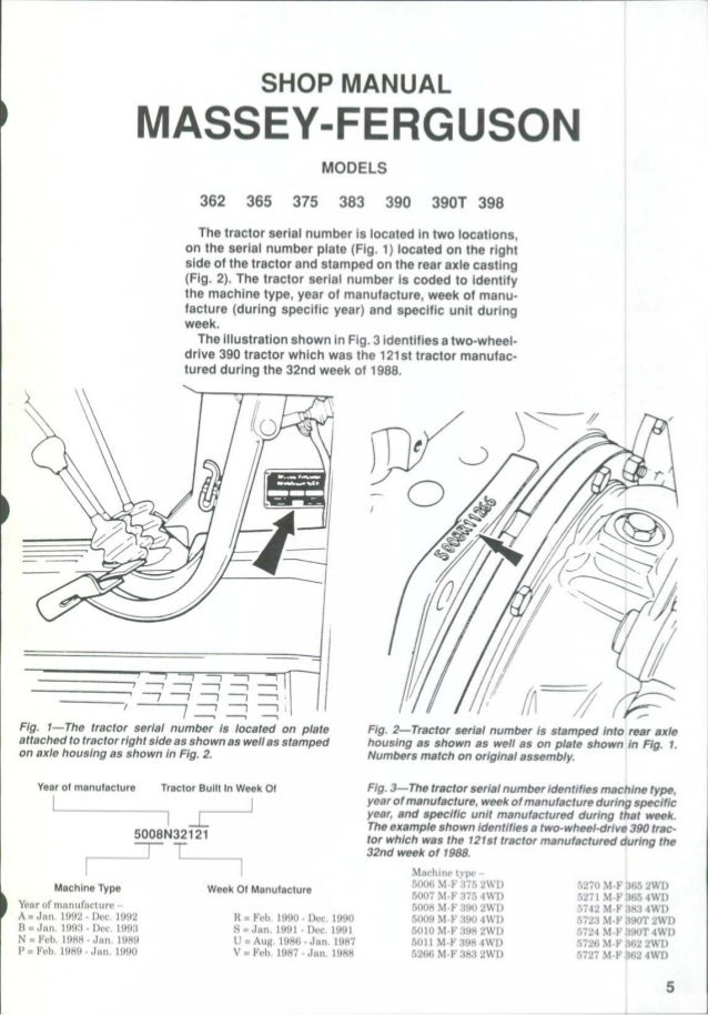
Remove cap 2 or 3—Fig. Insert the long sec- tion of drive shaft into guard, then assemble sliding coupling at rear, making sure that arrows on drive shaft and sliding coupling are aligned. Lubrication Mainshaft Output Shaft and Gears. The exampie shown identifies a two-wheei-drive 390 trac- tor which was the 12'ist tractor manufactured during the 32nd weei of 1988. All work should be performed with great care and in a clean working area with adequate lighting. Remove dust shield 12 , seal 9 and inner bearing cone 11.
Massey Ferguson 383 Engine Service Manual

To remove front axle assembly, first remove any front mounted equipment, guards, weights and weight frame. Service Manual for Massey Ferguson 383 Engine This Service Manual contains 122 pages of helpful information. Copyright © 1997-2019 Yesterday's Tractor Co. Be sure to install cap 2 or 3 securely. On 362 models, axle extension and hydrostatic steering cylinder bracket retaining screws 1—Fig. Insert the long sec- tion of drive shaft into guard, then assemble sliding coupling at rear, making sure that arrows on drive shaft and sliding coupling are aligned. Track adjusting screw and locknut 2 and cylinder bracket and axle extension screws 1 must be properly installed and tightened.
Massey Ferguson
Be careful not to lose shims which may be located be- tween front support casting and front of engine. Support the axle with a suitable jack to prevent tipping while permitting the axle to be lowered and moved safely. The descriptions are brief but precise and are supported by photographs, notes, drawings and schematics, as well as exploded and sectional drawings. Following them will help assure reliability. Removal of wheels, spindles and axle extensions will reduce weight and may make han- dling the center member easier; however, the com- plete axle assembly can be removed as a unit. Range Change Unit Upper Shaft 166 Range Change Upper Shaft Bearing Preload. Attach a hoist or other supporting device to the front support, then unbolt and separate the front support from the front ofthe engine.
Massey Ferguson 383 Engine Service Manual

Axle pivot bushings are located in axle of 365-398 models. You will be able to use the search function to browse the manual and print out your needed pages. Unscrew seal retaining ring from the slid- ing coupling, remove sliding coupling from rear end of drive shaft, then remove drive shaft from guard tube. There are some differences between the Front-Wheel Drive Systems used on these models that will be referred to in the servicing instructions which follow. It picks up where the service manual leaves off. Plus, all of our new, rebuilt and used parts come with our 1-year warranty.
MASSEY FERGUSON 362 365 375 383 390 390T 398 Tractor Shop Service Manual

Final Drive Rear Planetary Hub - Each Side. I Front wheel tread width is adjustable to seven different widths by relocating axle extensions and changing length of track rod using the preexisting attachment holes. John Deere and its logos are the registered trademarks of the John Deere Corporation. Pto Lower Shaft Front Bearing and Retainer Reverse Idler Gear and Shaft Shifter Rails and Forks Top Cover Tractor Rear Split Transmission Removal. If wheels are reversed, they must be moved to opposite sides oftractor to maintain correct tire tread direction. To remove front axle support from 365-398 models, first remove any front mounted equipment, guards, Fig, 13—Use a feeler gauge to measure gap A between the lower ears of casting and four-cylinder engine of 365-398 models. Balance of reassembly is the reverse of dis- assembly.
Massey Ferguson

Appropiate service methods and correct repair procedures are esential for the safe, reliabe operation of all motor vehicles as well as the personal safety of the individual carrying out the work. The track rod assures that both left and right wheels turn in unison, and the distance between ends of track rod establishes front wheel toe-in. This is a critical tool for operating and maintaining your machine. Nut retaining ball-joint of track rod end in the steering arm should be tightened to 78-86 N. Range Change Unit Upper Shaft 166 Range Change Upper Shaft Bearing Preload. Measure any Paragraphs 7-9 rgap A—Fig.