Mercury mariner 75 hp outboard manual. Mercury Mariner Outboard Manual 2019-02-15
DOWNLOAD 75HP OUTBOARD REPAIR MANUAL

Install cylinder head cover and driven sprockets. Re-install driven sprockets and timing belt. Each 75hp engine repair manual covers every aspect of repair. If bearing is rusted or does not roll freely, replace 11. Forward Gear Bearing Race 1. Remove hoses to fuel pump and oil injection pump. Remove throttle cable anchor screws and remove cable guide.
DOWNLOAD Mercury Outboard PDF Repair Manual

The maximum allowable opening between reed and General Information reed-block is 0. Loosen cam follower adjustment screw. For further information on how we use cookies and how to change your browser settings, please read our Cookie Policy. Measure and record the exhaust valve clearance for cylinders 2 and 4. Tighten set Engine is timed while cranking engine with starter screw securing cam follower.
Mercury 75 90 Hp 4 Stroke Outboard Repair Manual [Improved]
Reinstall electrical panel access cover and screws. Position throttle arm slot to face stop harness exit barrel to tube with allen screw approximately hole in tiller handle. Assembly Pinion Gear Locating Tool 91-12349A2 10. This must be checked with a flat blade feeler gauge, as shown. This new base does not require gaskets as it has a sili- cone impregnated seal on the top and bottom.
Mercury 75 90 Hp 4 Stroke Outboard Repair Manual [Improved]

Drive pin in until flush. All Cover Bolts: 18 lb. No Voltage Indicated: Connect Voltmeter red lead to Point 4 and Battery Voltage Indicated: black lead to ground. Refer to Section 2 - this manual. Open manual release valve three turns maxi- mum counterclockwise and position trim rod to full up position.
Mercury Mariner Outboard Manual

Place shock absorber each clamp bracket. Using a suitable punch, drive lower pivot pin into 6. Do not extend tilt ram. After engine break-in if necessary , raise or lower outboard one position at a time to attain best Determining Recommended Outboard performance. Torque special Locknuts must be used with bolts to secure bolt to 20 Ib.
Mariner Outboard Marine Service and Repair Manuals from Clymer

Lift motor from end cap. Install trim system, starboard transom bracket, and tilt tube nut. Make certain battery is fully charged. Motor and Electrical Remove screws. Remove camshaft caps and camshafts.
Mercury Mariner 75
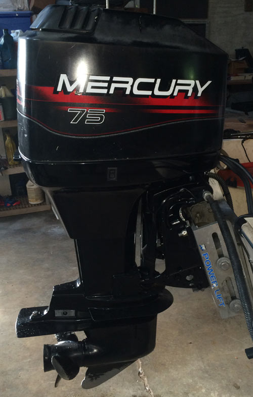
Check bearing surfaces of propeller shaft for pit- ting or wear. Install mounting bracket a to engine with 2 bracket for steering cable mounting tube to pro- spacers d , 2 locking retainers b and 4 bolts c. Model 70 Model 75 Model 80 Model 90 Horsepower 70 52. Disconnect link arm and remove trigger. Position access hole as shown. Disassembly Trim Rod Removal 1.
Mariner Outboard Marine Service and Repair Manuals from Clymer
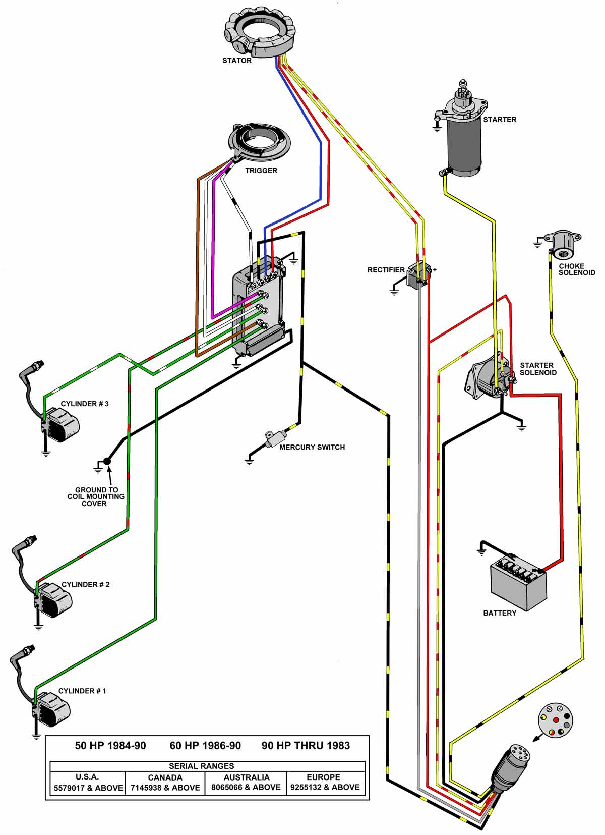
Make certain all connections are tight and corro- Electrical System sion free. Remove thermostat housing and components. Plug remote control harness connector into en- Connecting Engine Wiring gine harness connector, then secure connector in Harness and Routing of place with retainer as shown. Tap new cross pin in until flush. Check battery voltage at Description battery with engine running. Use piston ring expander 91-24697 to remove rod and rod cap bolt holes are threaded.
MARINER 70 SERVICE MANUAL Pdf Download.

Attachment Kit Installation Complete 2. Remove screws securing plate to trim rod piston and O-ring. Remove race shim s using Slide 1. Paint any exposed metal surfaces to prevent release valve will clear bracket when power trim corrosion. Check that plug-in connectors are fully engaged.
DOWNLOAD 1965
Boss Magnum, Twin Drag, 6:1 Retrieve. . If zero 0 ohms full continuity. Replace drive shaft if splines are worn or twisted. Adjust cable barrel to attain the same length be- Throttle Cable Installation and tween cable barrel and hole in end of cable guide Adjustment to Engine as exists between barrel retainer and shift actua- 1. Apply Quicksilver Liquid Neoprene 91-25511--2 in tilt ram end.