Automotive electrical wiring standards. Automotive Electrical Wiring: What are the standard sizes, number and thickness of strands for automotive wires? 2019-02-04
Understanding the types of Automotive Wire

I usually replace these with 10 awg heavy stranded wire if the power demand on them is close to the maximum. Identifying the color of the wire is important for accurate diagnosis. These measurements are often used during diagnosis, or when to solve problems. See our selection of Battery Cable 6. Automotive Wiring Diagrams and Electrical Symbols At first glance the repair diagram may not convey how the wires use many colors and diameters. Most trailers use a common coloring system that uses Green, Yellow, Brown, and White for the various lighting functions.
Wiring Standards, Codes and Specifications
If necessary, make a disposable copy of the diagram, then mark it up with colored pens or pencils until you understand how the circuit works. For example, a few basic symbols common to electrical schematics are shown as: 1 Switch, 2 Battery, 3 Resistor and 4 Ground. Break this diagram down and you can see how it can work for you. What is Adobe Digital Editions? They're arranged from top to bottom, so we can clearly see how the current flows through the circuit. In fact, an electrical symbol may have a slight resemblance to the actual component or its main function. These refer to the actual locations of the ground connections indicated in the diagram.
Automotive Wiring Colors
Bookmark or share this page and come back later. See our selection of Speaker Wire 5. Also discover what gives me the right to talk about automotive wiring diagrams. Let's look at one more schematic diagram, this time the backup light circuit in Fig. However, your car will not start or run without it.
Basic wire color guidelines

At the bottom of the diagram, note the circled numbers 7 and 8. The battery symbol appears to be made of layers or plates, common to internal battery construction. It's not mechanical, and therefore, it's unfamiliar territory. When the system involved is more complicated, several circuits may be included in the same diagram. . How do I purchase an eBook? View the demo video for this program that puts. Information about wire colors, terminal numbers, connectors, etc.
What are the basics to know for wiring harness design standards?

These symbols are universal, and memorizing them or having a copy handy is the best way to make sure you are looking for the right information. Take a look at my page about. No, unfortunately we cannot accept returns for eBooks. However, the abbreviated text labels or codes placed next to the symbols and lines help you out further by providing descriptions or location information. However, with a full understanding of principles and operation, diagnosis will be easier and faster.
Automotive Electrical Wiring: What are the standard sizes, number and thickness of strands for automotive wires?

Most of the stuff I work on seems to use Black, red, Black with a red stripe and red with a black stripe. These symbols represent the switch, battery, resistor and ground. The second most helpful thing is circuit numbers on the wires. The specifics of the wire coloring are dependent on the make, model and even year of the specific vehicle under consideration. Starter Circuit Diagram Things like current flow, voltage drops and common symbols are covered well. Now lets get back to the diagram issues. Each copper wire core is composed of smaller gauge strands of pure copper creating high conductivity, flexibility, and durability.
Automotive Wiring Colors

Advanced diagrams also will indicate the amps and circuit path. After installing Adobe Digital Editions on your device, you must authorize it. It also helps in future diagnosis of problems. One story - I spend one whole day trying figure out why a track loader would not move. What is the Bluefire Reader App? This video shows you how to stop wasting fuses and quickly find.
Wiring Standards, Codes and Specifications
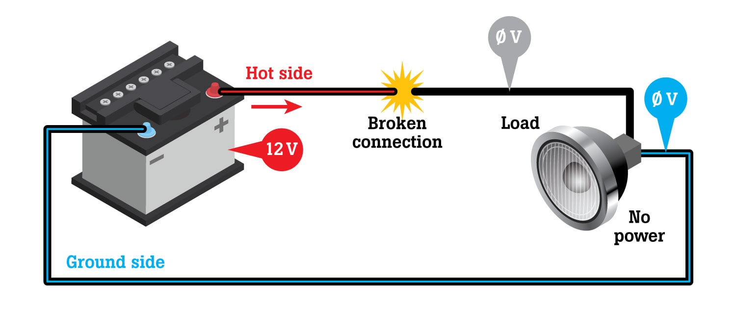
Learn about testing with a. Nevertheless, being aware of the color of a wire remains important. But when you understand the underlying system and standards that were used to design the vehicles and the diagrams, it's not as tough as it first seems. The easy answer is it depends on the voltage and amperage that the wire will have to carry, as with any electrical wiring. These lines actually represent current flow in and out of components connection points.
Automotive Wire

This is the method I use every time I break out a Find out more about me and this website. The first article explains the basic principles of electricity. I then get into using ohms law to determine voltage, current, resistance, and voltage drop. And to make matters worse they hid the damn relay under a bolt on kick panel but didn't show it in the manual! One guy was upset, because I mentioned using a test light instead of a meter. To oversimplify the challenges involved, how do you get an American assembly line to crank out parts for a European car? If you are looking for extra durability, this is a good choice. Again, it's a current flow diagram, with all of the circuit components laid out end to end. The amazing part is, these mileage improvements came at the same time as horsepower and torque increases.